


Working Principles of Common Industrial Flowmeters
Electromagnetic · Vortex · Ultrasonic · Mechanical — an easy-to-understand introduction
Every day, a wide variety of substances are distributed through piping systems, and many of them are closely related to our daily lives — water, natural gas, oil, and so on. Because fluids in pipelines often have completely different properties, different measuring principles are required. The most common flowmeter types are:
l Mechanical flowmeters
l Electromagnetic flowmeters
l Vortex flowmeters
l Ultrasonic flowmeters
The following sections explain the working principle and key characteristics of each type.
1. Mechanical Flowmeters
The mechanical flowmeter is what we commonly know as a "water meter". Inside the meter there is a rotating mechanism: flowing liquid drives the internal impeller to rotate, and the flow velocity is proportional to the rotational speed — the faster the impeller spins, the greater the flow passing through the pipe.
In addition, some mechanical flowmeters can generate pulse signals that represent the flow information and transmit them to a PLC.
However, because a mechanical flowmeter contains moving mechanical parts, it is not suitable for sewage or liquids containing solid particles.
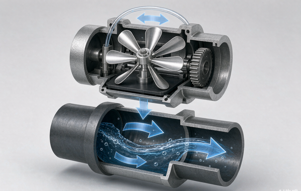
Figure 1. Cutaway view of a mechanical (impeller-type) flowmeter: flowing water drives the internal impeller, whose speed is proportional to the flow rate.
2. Electromagnetic Flowmeters
Electromagnetic flowmeters are very common in industry. The measured medium must be water or another electrically conductive liquid. They contain no moving parts, and their working principle is directly related to their name — they are based on the law of electromagnetic induction, i.e. Faraday's law:
E = B × L × V
Two excitation coils are arranged at the top and bottom of the meter to generate a constant magnetic field B. As a result, the positively and negatively charged particles in the fluid are acted upon by the magnetic field and separated.
At the same time, a pair of electrodes on the left and right sides of the meter detects the induced electromotive force. Based on the measured EMF and the distance L between the two electrodes, the flowmeter calculates the flow velocity V of the liquid and finally converts it into flow information.
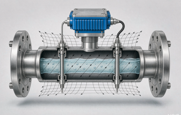
Figure 2. Electromagnetic flowmeter: excitation coils generate a magnetic field, and the electrodes detect the induced voltage of the conductive liquid (E = B × L × V).
3. Vortex Flowmeters
First, what is a "vortex street"? A vortex street — also known as the Kármán vortex street or Kármán vortex trail — is a physical theory proposed by the Hungarian-American aerodynamicist Theodore von Kármán, who was also the doctoral supervisor of Qian Xuesen, one of the most important figures in China's aerospace history.
When a bluff body (shedder) is placed in a flowing fluid, an unstable boundary-layer separation occurs under certain conditions: two staggered rows of vortices are shed alternately on the two sides downstream of the bluff body. The vortices on one side rotate clockwise while those on the other side rotate counter-clockwise. The two rows of vortices are arranged alternately, like street lamps on both sides of a road — hence the name "vortex street". In everyday life, the same Kármán vortex street can be observed when river water flows past an obstacle.
Back to the main topic: vortex flowmeters make use of exactly this principle.
A bluff body is installed at the inlet of the meter to generate the vortex street. The vortices then strike the sensor probe behind the bluff body, which records the vortex frequency. The higher the flow velocity, the higher the vortex frequency — in other words, there is a fixed relationship between fluid velocity and vortex frequency. Finally, the flowmeter calculates the flow information through internal computation.
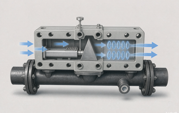
Figure 3. Vortex flowmeter: the triangular bluff body sheds alternating vortices whose frequency is proportional to the flow velocity.
4. Ultrasonic Flowmeters
Ultrasonic waves are sound waves whose frequency lies above the range audible to the human ear — hence the name.
Sound waves have a special property when travelling through a fluid: they propagate faster with the flow (downstream) and slower against the flow (upstream). This is easy to understand — sound is a mechanical wave, and its speed is not fixed like the speed of light for electromagnetic waves.
Ultrasonic flowmeters make use of exactly this property. A pair of ultrasonic transducers is mounted on the pipe, one transmitting and one receiving, and the time difference is measured. This time difference is proportional to the flow velocity; the velocity is then obtained through mathematical conversion, and the flow rate is calculated. This measuring method is also known as the "transit-time method".
4.1 Clamp-on Installation
The transducers described above are installed inside the pipe. There is also a clamp-on version, in which the sensors are mounted on the outer wall of the pipe. This is easy to install and well suited for retrofit projects.
4.2 Doppler Ultrasonic Flowmeters
For fluids containing solid particles, a Doppler ultrasonic flowmeter can be used. This type applies the Doppler effect: when a sound wave encounters a solid particle on its propagation path, the wave is reflected and its wavelength and frequency are changed — the so-called frequency shift. The higher the velocity, the greater the frequency shift. The flow velocity can therefore be calculated from their mathematical relationship.
The Doppler effect is also widely used in radar technology — military enthusiasts will certainly have heard of pulse-Doppler radar.
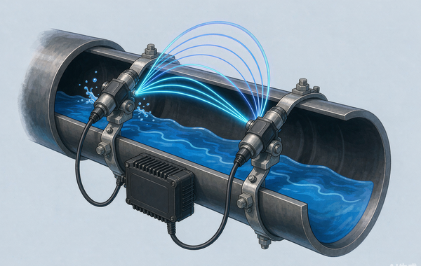
Figure 4. Clamp-on ultrasonic flowmeter: paired transducers mounted on the outside of the pipe measure the transit-time difference of the sound beams.
5. Summary
|
Type |
Measuring principle |
Suitable media |
Features and limitations |
|
Mechanical flowmeter |
Liquid drives an impeller; speed is proportional to flow |
Clean liquids (e.g. tap water) |
Simple structure, pulse output; moving parts, not suitable for sewage or particle-laden media |
|
Electromagnetic flowmeter |
Faraday's law of electromagnetic induction, E = B × L × V |
Water and conductive liquids |
No moving parts, widely used in industry; not suitable for non-conductive media |
|
Vortex flowmeter |
Kármán vortex street; vortex frequency proportional to velocity |
Steam, gas and liquids |
Simple structure without moving parts; sensitive to low flow rates and pipe vibration |
|
Ultrasonic flowmeter |
Transit-time method / Doppler method |
Liquids (Doppler type suits particle-laden media) |
Clamp-on installation possible, ideal for retrofits; influenced by the acoustic properties of the fluid |
 Trumsense High-Precision Ultrasonic Water Level Meter: Smart and Reliable Level Measurement Solution
 Say No to Simple Assembly——Pressure Transmitter and Submersible Liquid Level Meter
 Trumsense® M18 or M30 Ultrasonic Sensor Module With SS304 or ABS Housing Optional Outputs for NPN or PNP or 4 to 20mA or 0 to 5V or 0 to 10V or RS485
 Trumsense DC 12 to 24V Power Supply WS02 WS03 Capacitive Type Contactless Liquid Level Sensor For Flat Container or Pipes
